
Network Layer
Forwarding and Routing
The role of the network layer is simple - To move packets from a sending host to a receiving host.
Forwarding: When a packet arrives at a routers input link, the router must move the packet to the appropriate output link.
Routing: The network layer must determine the route or the path taken by packets as they flow from a sender to a receiver. The algorithms that calculate these paths are referred to as routing algorithms.
Connection Setup: Some network layer architectures require the routers along the chosen path from source to destination to handshake with each other in order to set up state before the packets can flow. In the network layer this process is referred to as connection setup.
Forwarding refers to the routers local action of transferring packet from an input link to the appropriate output link. Routing refers to the network wide process that determines the end-to-end path that packets take from source to destination.
Every router has a forwarding table which helps the router to forward the packets by examining their header.
How are the forwarding tables configured in the routers?
This is a critical issue, which exposes the important interplay between routing and forwarding. The routing algorithm determines the values that are inserted into the routers forwarding table.
We reserve the term packet switch to mean a general packet switching device that transfers the packet from the input link to an output link.
Link layer switches base their forwarding decision on values in the fields of the link-layer frame; switches are thus referred to as link-layer devices
Routers, base their forwarding decision on the value in the network layer field. Routers are thus network-layer device.
Network Service Models:
The network service model defines the characteristics of end-to-end transport of packets between sending and receiving end-systems.
Services that could be provided by the network layer include:
Guaranteed delivery: all packets will eventually reach the destination.
Guaranteed delivery with bounded delay: guaranteed delivery with specified host-to-host delay bound.
In-order packet delivery
Guaranteed minimal bandwidth
Guaranteed Maximum jitter: the spacing between the transmission between two successive packets at the sender varies by no more than a specified value
Security Services
There are countless variations possible
The Internets network layer provides best-effort service which is same as no service at all.
Other network architectures have defined and implemented service models that go beyond the internets best-effort-service.
ATM CBR - Constant Bit Rate: With CBR, a flow of ATM packets is carried across the network in such a way that a cells(hosts) end-to-end delay, variability in packets end-to-end delay(jitter), and the fraction of packets that are lost or delivered late are bounded.
ATM ABR - Available Bit Rate:
ABR can be characterised as being slightly better than the best-effort-service. Packets can get lost under ABR, however packets cannot be reordered, and a minimum packet transmission rate is guaranteed.
Virtual Circuits and Datagram Networks
A network-layer can provide connectionless service or connection oriented service between two hosts. Network layer connection and connectionless services in many ways parallel the transport-layer services but there are crucial differences.
The transport layer connection-oriented service is implemented at the edge of the network in the host systems. The network layer connection-oriented service is implemented in the routers in the network cores as well as in the end-systems
Networks that provide only a connection-oriented service at the network layer are called virtual-circuit (VC) networks.
Networks that provide only a connectionless service at the network layer are called datagram networks.
Virtual-Circuit (VC) Networks:
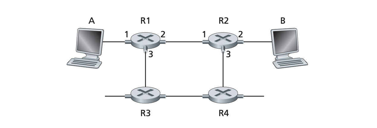 Virtual circuit Networks use connections at the network layer. These connections are called virtual circuits (VCs).
A VC consists of
- A path which is a series of links and routers between the source and destination hosts
- VC number, one number for each link along the path
- entries in the forwarding table in each router along the path
A packet belonging to a VC will carry a in its header. Because a VC may have a different on each link, each intervening router must replace the of each traversing packet with a new .
In a VC network, the routers must maintain connection state information for the ongoing connections. Specifically, each time a new connection is established across a router, a new connection entry must be added to the routers forwarding table; and each time a connection is released, an entry must be removed from the table.
There are three identifiable phases in a VC:
- VC Setup:
- The network layer determines the path between the sender and receiver.
- determine the for each link along the path
- Add an entry in the forwarding table of each router in the path
- Data Transfer:
- VC is established so the packets can flow
- VC Teardown:
- Sender informs the network layer to terminate the connection
- Update the destination network layer
- update the forwarding table of the routers on the path.
In VC setup, the routers along the path between the two end systems are involved in VC setup and each router is fully aware of all the VCs passing through it.
The messages that end systems send into the network to initiate to terminate a VC, and the messages passed between the routers to set up the VC are known as signalling messages, and the protocols used to exchange the messages are often referred to as signalling protocols.
Datagram Networks:
In a datagram network, each time and end system wants to send a packet, it stamps the packet with the address of the destination end system and then pops the packet into the network.
As a packet is transmitted from source to destination, it passes through a series of routers. Each router uses the packets destination address to forward the packet.
the router matches a prefix of the packets destination address with the entries in the table; if there is a match the router forwards the packet to a link associated with the match.
When there are multiple matches, the router uses the longest prefix matching rule, it finds the longest matching entry in the table and forwards the packet.
The forwarding table are configured by the routing algorithms, which typically update tables every one-to-five minutes.
Because forwarding tables in datagram networks can be modified at any time, a series of packets sent from one end system to another may follow different paths through the network and may arrive out of order.
Whats Inside a Router?
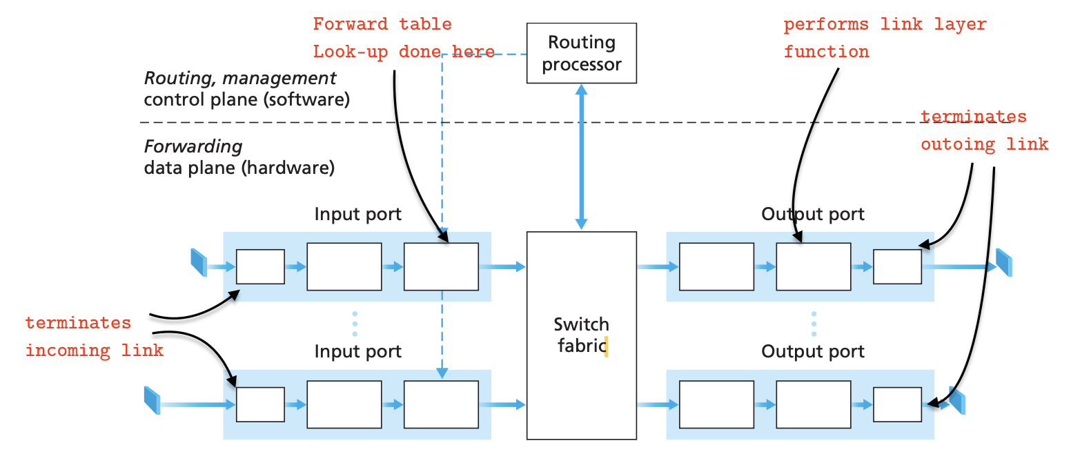
Input Port: The lookup function is performed at the input port. This will occur in the rightmost box of the input port. Here the forwarding table is consulted to determine the router output port to which an arriving packet will be forwarding via the switching fabric.
Input Port Queuing When the switching fabric is slower than the input ports combined, it leads to queuing at input port.
Switching Fabric: The switching fabric connects the routers input ports to its output ports. Control packets are forwarded from an input port to the routing processor.
Output ports: Stores the packets received from the switching fabric and transmits them by performing necessary link and physical layer functions.
Output port Buffering: Buffering when arrival rate via switch exceeds output line speed.
How much buffering? With N flows, buffering =
Routing processors: Executes routing protocols, maintains routing tables and attached link state information. Incoming reachability information from RIP/OSPF/BGP… is used to compute the RIB (Routing Information Base)
RIB Routing Information Base
Routers can have multiple RIB, one for each routing protocol. these individual TIBs are consolidated into one global RIB or into FIB.
Contents:
- Network ID of the destination subnet
- Cost/Metric for hop
- Next hop gateway or end-system