
cheatsheet
Application Layer:
| Type | Name | Value |
|---|---|---|
A | hostname | IPv4 Address |
AAAA | hostname | IPv6 Address |
NS | Domain | hostname of Authoritative DNS Server |
CNAME | alias hostname | Canonical hostname |
PTR | IP Address | hostname |
Transport Layer:
UDP header:
- allow multiplexing and demultiplexing.
- field specifies the number of bytes in the UDP segment (header + data)
- is used to check whether errors have been introduced in the segment.
TCP Header:
- , : for multiplexing and demultiplexing
- , : for implementing
- : specifies the length of the TCP header in words. Header length can be variable due to the field.
- The field contains .
- the segment contains an ACK
- , and are used for connection setup and teardown
- indicates the receiver should pass the data to the upper layer immediately.
- is used to indicate there is data in the segment that the sending side upper layer has marked as urgent.
- is used for flow control. indicates the number of bytes the receiver is willing to accept.
Timeout:
Congestion control
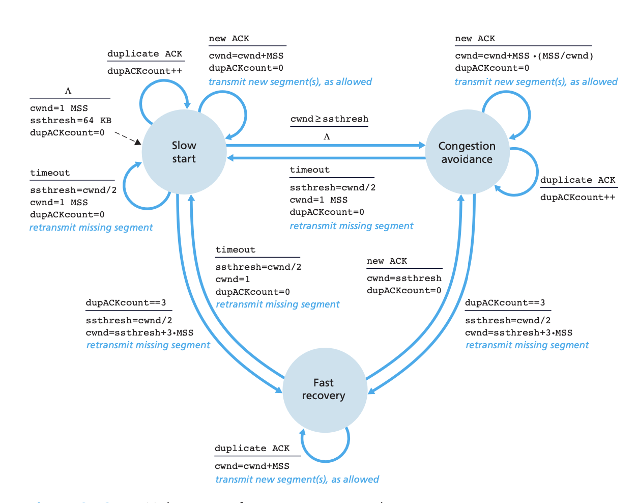
Network Layer
- Classful Addressing:
| CLASS | #bits NID | #bits HID | #IP ADDr | 1st Octet Range #N/W | #N/Ws | #HOSTS per N/W |
|---|---|---|---|---|---|---|
| A | 8 | 24 | 2^31 | 0 - 127 | 2^7 | 2^24 - 2 |
| B | 16 | 16 | 2^30 | 128 - 191 | 2^14 | 2^16 - 2 |
| C | 24 | 8 | 2^29 | 192 - 223 | 2^21 | 2^8 - 2 |
| D | 24 | 8 | 2^28 | 224 - 239 | X | X |
| E | 24 | 8 | 2^28 | 240 - 255 | X | X « RESERVED FOR SPECIAL PURPOSE |
Private IP Address Range:
- to
- to
- to
IPv4 Segment:
- - specify the IP Protocol version
- - Header length in is variable due to
- - allows different types of IP datagrams (requiring low delay, high throughput) to be distinguished from each other
- - is the total length of the IP Datagram (). Imposes an upper bound to the datagram length ().
- - These fields are related to IP Fragmentation
- - used to ensure that datagrams do not circulate forever in the network. The field is decremented by each router. If then drop then datagram.
- - Value indicates the specific transport layer protocol the data should be passed
- - Helps in detecting error bits in a received IP datagram Router computes the header checksum for each received IP dataframe and detects an error condition. Drop the datagram for which error is detected Checksum must be recomputed and stored again at each router, as field and may change
- - Allows IP header to be extended
IPv6 Segment:
- : field identifies the version.
- : field is similar in spirit to the
- : field is used to identify the flow of the datagram
- : value is treated as unsigned integer giving the number of bytes in the datagram following the fixed header.
- : field is similar in spirit to the field
- : Similar to field
- : various formats of address
DHCP
- server discovery: Done using , broadcasted () by the client.
- server offer(s): A server responds to the client with a , which is also broadcasted on the subnet.
- Request: client responds a selected offer with a , echoing back the configuration parameters
- : The server responds with a , confirming the parameters.
Steps in adding an outside-AS destination in a router’s for- warding table, Pg410 Add flowchart for determining the best path for BGP BGP Route Selection
| Own routes | Customers routes | Siblings routes | Providers Routes | Peers routes | |
|---|---|---|---|---|---|
| Exporting to Provider | Y | Y | Y | N | N |
| Exporting to Customer | Y | Y | Y | Y | Y |
| Exporting to Peer | Y | Y | Y | N | N |
Link Layer
Multiple Access Protocols:
- ALOHA:
- Slotted ALOHA:
- CSMA/CD:
Ethernet Frame Structure:
- : - Maximum Transmission Unit for ethernet is
- : Contains the MAC address of the destination adapter
- : Contains the MAC address of the adapter that transmits the frame into the LAN
- : The type field permits ethernet to multiplex the network layer protocols.
- : Cyclic Redundancy Check is used for error detection
- : The ethernet frame begins with an preamble field.
Multimedia Networking
DASH Working:
- The client first requests the manifest file and learns about the various versions.
- The client then selects one chunk at a time by specifying a URL and a byte range in an HTTP GET request message for each chunk.
- While downloading chunks, the client also measures the received bandwidth and runs a rate determination algorithm to select the chunk to request next.
VOIP - Removing Jitter:
- - playtime, - time of generating, - fixed delay usually
- Fixed Playout Delay:
- Adaptive Playout Delay: For each talk spurt:
Datacenter Networking
- Bisection Bandwidth
- Full Bisection Bandwidth
- Over subscription Ratio